Products
From Voice and data transmission, cellular communications, and satellite communication, to the purification of LCD panels or semiconductor wafers…
Ka-Band Ext. Ref. PLL LNB
Ku-Band PLL LNB
High Power Waveguide Components
High Power Waveguide Circulator / Isolator
High Power Rotary Joint
Ku-Band Ext. Ref. PLL LNB
High Power Dummy Load
C-Band PLL LNB
-
Ka-Band Ext. Ref. PLL LNB
Ka-Band Ext. Ref. PLL LNBKa-Band Ext. Ref. PLL LNB
- Model: SPCR7401CF/CN
- 20.2 to 21.2GHz
No Item Specification 1.0 Power 1.1 DC Voltage 15 to +24Vdc 1.2 DC Current 400mA max. 1.3 Interface DC power will be multiplexed on a single coaxial connector with the IF and 10MHz reference signals. 2.0 RF Input 2.1 Frequency 20.2 to 21.2GHz 2.2 Inteface WR-42 waveguide flange with O-ring and threaded screw holes. 2.3 Input VSWR 1.35:1 max., LNB is Powered Off 2.4 Lo Leakage -60dBm max at waveguide flange. 2.5 Desensitization The LNB shall suffer no more than 0.1dB of noise figure degradation with a signal of -20dBm (preliminary) in the transmit band, which is 30.0 to 31.0GHz. 2.6 Damage The LNB shall be able to receive a signal in the band of 20.2 to 21.2GHz at a level of -25dBm without damage to the unit. -
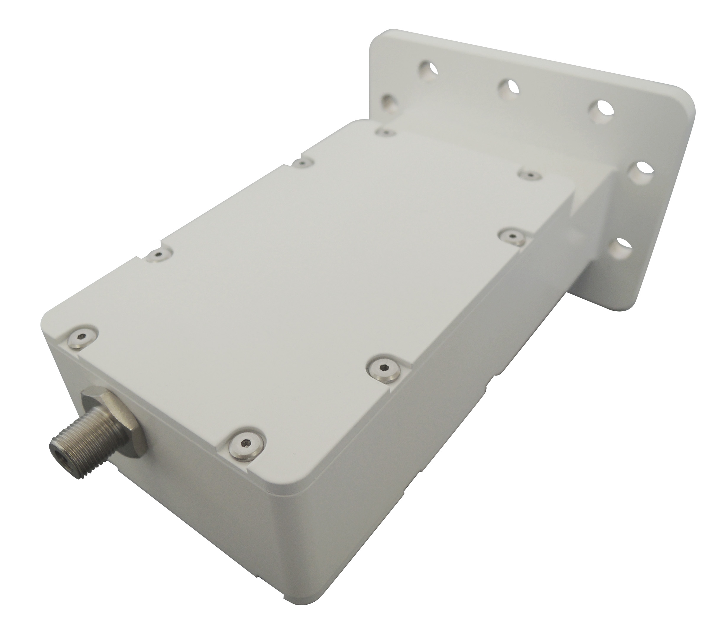
Ku-Band PLL LNB
Ku-Band PLL LNB- 1dB Gain Compression +10dBm
- Suitable for high data rate digital communication applications
- Low power consumption
- Low noise
No Item Specification -1 RF Input Frequency 11.70 to 12.20 GHz 12.25 to 12.75 GHz 10.95 to 11.70 GHz -2 IF Output Frequency 950 to 1450 MHz 950 to 1700 MHz -3 Local Frequency 10.75 GHz 11.30 GHz 10.00 GHz -4 Local Frequency Stability Standard: ±2.3ppm. max. @ -40oC to +60oC, +25oC Reference (SPCR5300) Option : ±0.5ppm. max. @ -40oC to +60oC, +25oC Reference (SPCR5302) avail in 11.7-12.2 GHz only -5 Local Phase Noise: Offset Frequency / Phase Noise 100 Hz / -70 dBc/Hz 1 kHz / -80 dBc/Hz 10 kHz / -85 dBc/Hz 100 kHz / -105 dBc/Hz -6 Noise Figure (+25°C) 0.8dB max. -7 Gain 55 to 70 dB Over Frequency & Temperature -8 Gain Ripple 1 dB p-p max per 36 MHz segment across the frequency band -9 1 dB Gain Compression Point +10 dBm min. -10 Spurious in Rx Band -140dBm max. @waveguide input excluding Rx out + 1 MHz measured at RF Input power -85dBm -11 Input Voltage +12 to +24 V supplied through center conductor of IF cable. -12 Current 200 mA -13 Input Interface WR-75,Waterproof – Mated with matching flange and O-ring -14 Output Interface Standard: F-Type, 75 ?, female, Waterproof Option: N-Type, 50 ?, female, Waterproof -15 Size 125(L) mm x 60(W) mm x 22(H) mm (4.9 x 2.3 x 0.8 in) without flange -16 Weight 340g (F-Conn) / 348g (N-Conn) -17 Operating Temperature -40°C to +60°C -18 Storage Temperature -40°C to +80°C -
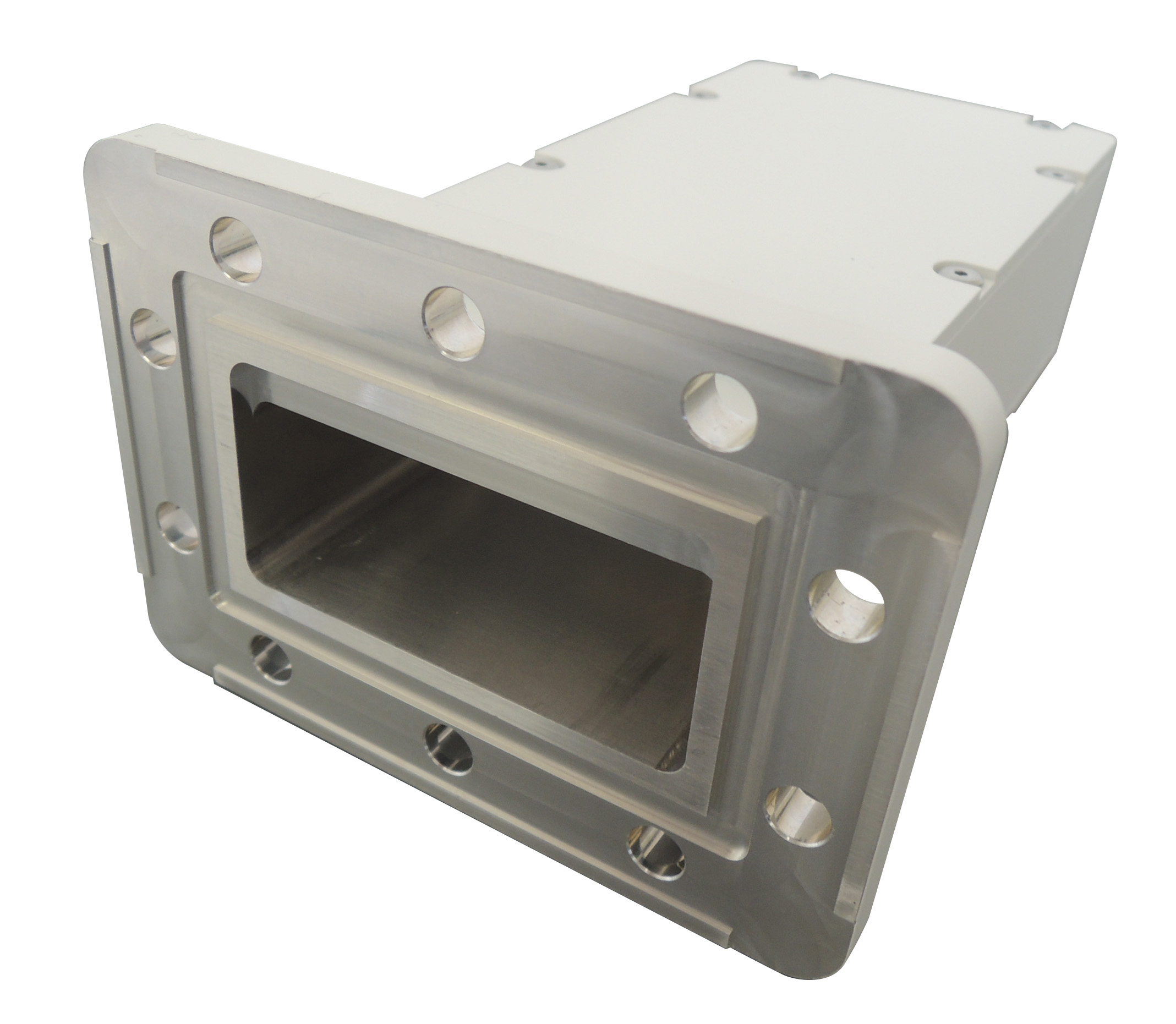
High Power Waveguide Components
High Power Waveguide ComponentsHigh power of megawatts, low loss Waveguide
- Low Insertion Loss, Low VSWR
- Customizable to EMS (Electro Mechanics Solutions) combined with flexes and couplers.
- Waveguide tube:Aluminum alloy, Brass, Oxygen-free copper (OFC)
- Waveguide thickness:Thin and Heavy Wall Waveguide Tubing
- Surface:Ag, Cu nickel
-
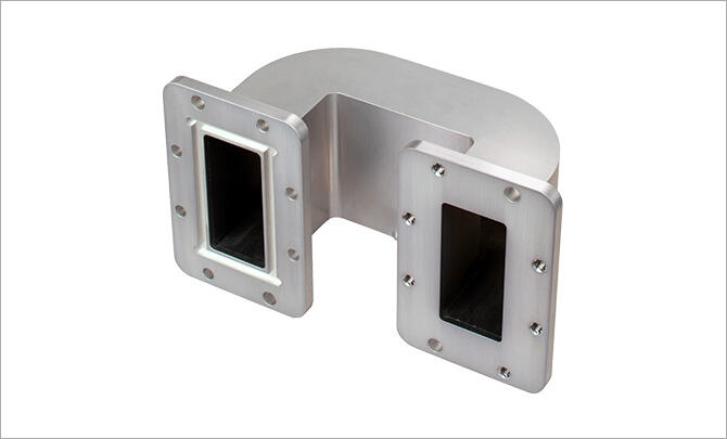
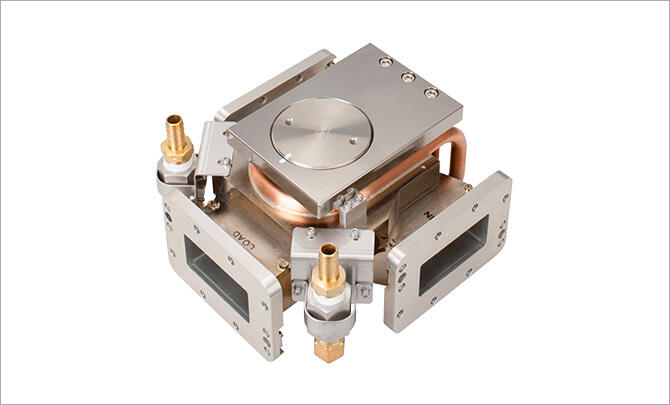
High Power Waveguide Circulator / Isolator
High Power Waveguide Circulator / IsolatorAchieves small size and low loss as a microwave power supply system component. Both 3-port circulator and 4-port circulator are possible. In addition to the general Below Resonance design, it is also compatible with Above Resonance for higher power.
- Megawatt class high power circulator / isolator
- Compatible with 4-port high-power circulators
- Cooling method supports water cooling and forced air cooling
-
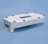
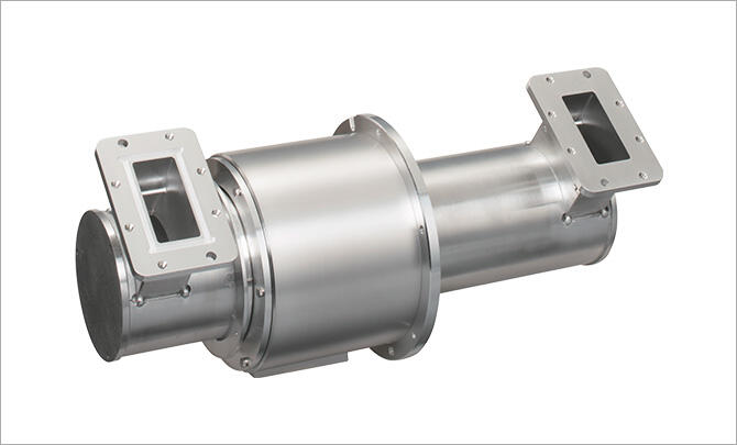
High Power Rotary Joint
High Power Rotary JointRotary Joint for High power of several ten megawatts which enable power loss to be stable by mode converting round to rectangular waveguide or rectangular to round one.
- MW High Power, Low loss
-
Ku-Band Ext. Ref. PLL LNB
Features:- 1dB Gain Compression +10dBm
- Suitable for high data rate digital communication applications
- Low power consumption
- Low noise
Electrical SpecificationsNo Item Specification 1.0 Power 1.1 DC Voltage 15 to +24Vdc 1.2 DC Current 400mA max. 1.3 Interface DC power will be multiplexed on a single coaxial connector with the IF and 10MHz reference signals. 2.0 RF Input 2.1 Frequency 20.2 to 21.2GHz 2.2 Inteface WR-42 waveguide flange with O-ring and threaded screw holes. 2.3 Input VSWR 1.35:1 max., LNB is Powered Off 2.4 Lo Leakage -60dBm max at waveguide flange. 2.5 Desensitization The LNB shall suffer no more than 0.1dB of noise figure degradation with a signal of -20dBm (preliminary) in the transmit band, which is 30.0 to 31.0GHz. 2.6 Damage The LNB shall be able to receive a signal in the band of 20.2 to 21.2GHz at a level of -25dBm without damage to the unit. -
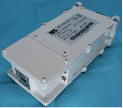
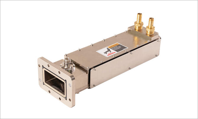
High Power Dummy Load
High Power Dummy LoadThe dry load can prevent water from entering the waveguide. Water load has a structure capable of absorbing a microwave, and can achieve stable VSWR even when high power is supplied.
- Mega Watt L band to X band
- Low VSWR
-
C-Band PLL LNB
Parameter Performance RF Input Frequency [GHz] 4.0 to 4.2 (Rejection Range 3.4 to 3.9) IF Output Frequency [MHz] 950 to 1150 LO Frequency [GHz] 5.15 Noise Temperature [K] 15 typ. 30 max. at 25℃ Phase Noise [dBc/Hz] -80 typ. at 1kHz
-85 typ. at 10kHz
-95 typ. at 100kHzGain [dB] 55 to 65 Input VSWR 2.5 typ. Output VSWR 1.8 typ. Output P1dB [dBm] +10 min. DC Supply Voltage [V] +12 to +24 Current [mA] 350 max. RF Input Interface CPR229 (with Groove) IF Output Interface F-connector female (75 ohm) Weight [g] Approx. 570 Size (L×W×H) [mm] 144×68×39 (without Flange) -